
DC Electromagnetic Brake DM Series – Adjustment, Drawing & Operation
DC Electromagnetic Brake is suitable for 220 Volts D.C. supply and is available for drum Diameters from 100mm to 80mm D.C. Electromagnetic brakes are used to retard or to stop moving loads or rotating mass, to prevent damage to men and equipment.
Features DC Electromagnetic Brake
- Robust construction and simple.
- Reliable braking action.
- Efficient transmission of forces.
- Brake shoe replacement without dismounting.
- Ease of maintenance.
- Ease of torque adjustment.
- Air Gap
The brake is released by a powerful, short-stroke electromagnet. The gap between the coil and the armature is to be maintained to about 0.3 mm. Brake coil is encapsulated with epoxy resin and is with ‘Class F’ insulation.
Technical Data
Class of insulation of Coil-’F’
Maximum operating voltage-660V
Rated supply -220V, D.C.
Section of Brake Size
Brake Torque of 180% to 250% of motor rated torque is sufficient for normal applications like cranes, hoists, and other material handling equipment. For Ct and LT drives, braking torque of 80% to 150% of motor rated torque will ensure braking without excessive noise and mechanical jerk.
Rated motor torque is given by
Mb=716.2xHP/RPM in kg-m, OR,
=9.55xkW/RPM in Newton-m.
Where, kW or HP is motor rated power and RPM is motor rated speed in revolutions speed per minute.
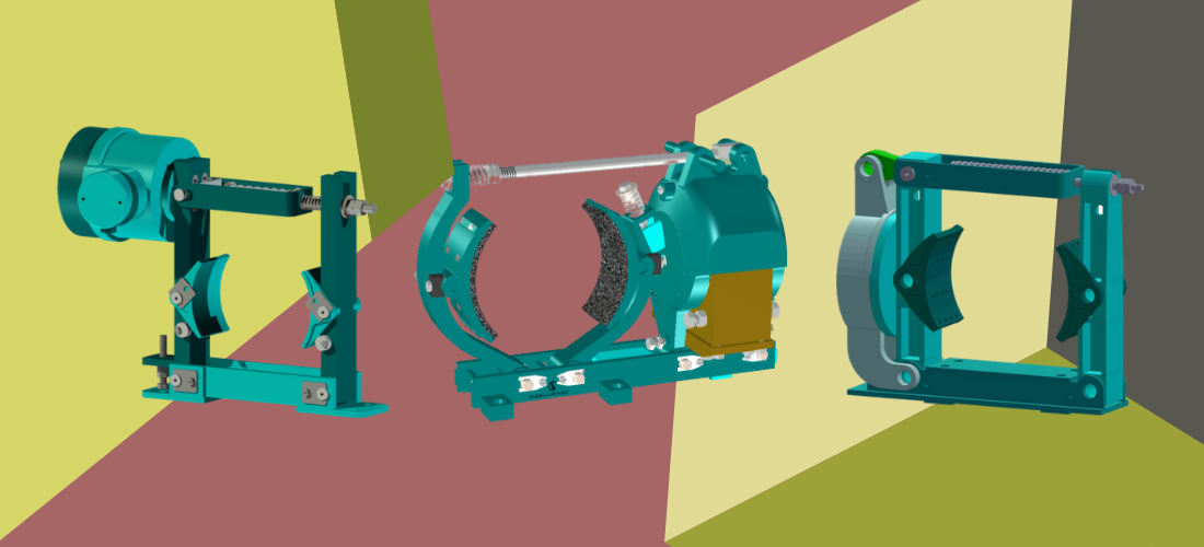
Construction
The Brake mounting base frame carries two operating arms, Main Arm and Side Arm, which are hinged to the base frame. Two Brake shoes that carry brake liner are hinged to each of the arms by Hinge Pin and a magnet coil is fitted in the magnet body and actuates the plunger which is pre-stressed by Brake Spring. The plunger is retained by a set of a tie-rod and nuts. The shoe settings screws and are to be adjusted such that the shoes maintain a clear air gap with Brake Drum in running condition. A Stopper screw is to be adjusted such that the Main Arm opening is restricted when the brake release and the brake shoes move away equally from the Brake Drum.
Operation
The magnet coil works on a rectified DC current and pulls in the plunger, under the effect of pre-loaded compression spring, when the DC current to coil is cut-off, either intentional(to apply brake) or accidentally due to sudden mains power failure. The arms move in and the brake lines on the brake shoes clamp on the rotating Brake Drum, under the effect of the spring force and arrest the Brake Drum. When the DC current to the magenta coil is restored, the plunger is pushed out from the magnet body. The plunger tie-rod then pushes first the Main Arm, and then the Side Arm away from each other and the brake shoes release the clamping force on the Brake Drum which is free to move.
Since the brake is applied by stored spring energy, which is activated by disconnecting the DC supply to the coil, this brake is called ‘Fail-to-safety’ Brake, which prevents the damage to the plant, Machinery, and personnel in the event of sudden power failure.
Installation
When the brake leaves the factory, the brake shoes and arms are set according to the Brake Drum diameter. To install the brake on the Brake Drum and the foundation, it is necessary to open the gap between the Brake shoes, so that the brake can be inserted on the Brake Drum. The stopper screw of the main arm and tie-rod nuts are to be loosened.
The brake is then inserted on the brake drum and is to be lowered and installed on the foundation bolts. The Brake is firmly fitted on to the foundation. Next, the Brake shoes are to be adjusted by suitably positioning the main and the side arms, until both shoes are set to a uniform air gap(1 to 1.5mm) over the brake drum, and the shoe setting screws and are suitably set. The Main Arm setting screw is to be adjusted such that the main arm, (which opens first, when the brake is released,) is constrained in its movement by the stopper screw, and the balanced stroke of the plunger is utilized for the opening of the Side Arm.
The Rectified DC supply cables for the magnet coil are suitably connected on the Terminals provided in the junction box on the magnet body.
The DC Electromagnetic Brake is ready for operation.
Maintenance
The DC Electromagnetic Brake needs very little maintenance as it has no working fluid, oil-seals, or any such components. When the brake liners wear out, they (along with the brake shoes)are to be replaced by a new set. The shoes can be removed by removing the hinge-pin and sliding out the worn-out shoe over the drum surface. The new shoe can be fitted in a similar manner.
This replacement of shoes can be done without dismantling the brake from the foundation.
DM100 to DM 315
| Brake Size | Drum Dia. mm | Brake Torque Kg-m | A | B | C | d | ØE | F | G | h | H | J | K | L | M | N | S | Wt. kg |
| DM100 | 100 | 1.6 | 391 |
70
|
125 |
13
|
145 | 240 | 260 | 100 | 272 |
6
|
40 | 4 | 65 | 8×8 | 110 | 16 |
| DM150 | 150 | 10 |
440
|
180
|
190
|
305
|
330
|
150
|
385
|
50
|
6
|
80
|
10×10
|
155
|
36
|
|||
| DM160 | 160 | 10 | ||||||||||||||||
| DM200 | 200 | 12.5 | 571 | 90 | 190 | 17 | 335 | 400 | 170 | 450 | 8 | 60 | 90 | 11×11 | 185 | 41 | ||
| DM250 | 250 | 35 | 600 | 110 | 245 |
21
|
245
|
430 | 500 | 200 | 510 | 10 | 70 |
8
|
105 | 12×12 | 220 | 70 |
| DM300 | 300 | 50 |
753
|
140
|
285
|
465
|
590
|
240
|
602
|
12
|
80
|
120
|
14×14
|
265
|
94
|
|||
| DM315 | 315 | 50 |
DM 400 to DM 800
| Brake Size | Drum Dia. mm | Brake Torque Kg-m | A | B | C | d | ØE | F | G | h | H | J | K | L | M | N | S | Wt. kg |
| DM400 | 400 | 120 | 948 | 180 | 300 | 25 | 355 | 504 | 780 | 320 | 660 | 90 | 90 | 250 | 300 | 520 | 340 | 240 |
| DM500 | 500 | 190 | 1111 | 200 | 375 | 25 | 450 | 575 | 915 | 400 | 823 | 115 | 100 | 315 | 375 | 640 | 375 | 364 |
| DM600 | 600 | 355 | 1312 | 240 | 450 | 38 | 522 | 675 | 1080 | 475 | 950 | 140 | 126 | 380 | 420 | 780 | 450 | 600 |
| DM700 | 700 | 575 | 1512 | 280 | 505 | 38 | 600 | 770 | 1215 | 550 | 1108 | 180 | 150 | 430 | 495 | 890 | 505 | 960 |
| DM800 | 800 | 910 | 1628 | 320 | 585 | 38 | 688 | 853 | 1420 | 600 | 1255 | 200 | 180 | 480 | 580 | 1020 | 585 | 1360 |